Adding an Auxiliary Audio Input to a 2005 Subaru Outback
I own a 2005 (fourth generation) Subaru Outback, I’ve had it since the fall of 2006 and it has been great. I have a little over 100,000 miles and do not plan to sell it anytime soon.
There is one thing that just kills me though. You cannot (easily [1]) change the radio in it…and it is just old enough [2] to have neither BlueTooth nor an auxiliary audio input. I’ve been carrying around a book of CDs with me for the past 8 years. I decided it was time to change that.
I knew that it was possible to “modify” the radio to accept an auxiliary input, but it involved always playing a silent CD, which I did not find adequate. I recently came across a post of how to do this in such a way that the radio functions as normal, but when you plug in a device to the auxiliary port it cuts out the radio and plays from the device. Someone else had also confirmed that it worked for them. Cool!
I vaguely followed the directions, but made a few changes here and there. Also, everyone online seems to make it seem like the radio is super easy to get out…I seriously think I spent at least two hours on it. There were two videos and a PDF I found useful for this task.

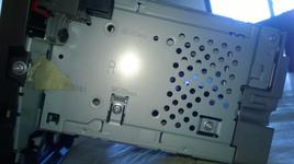
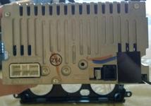
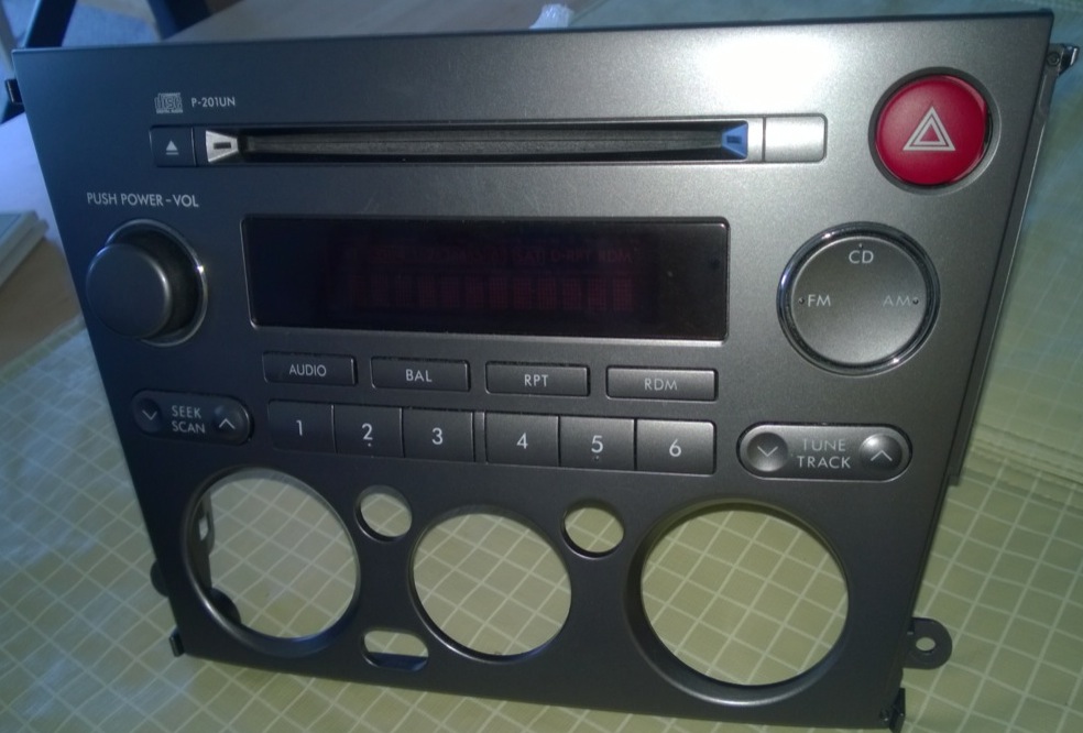
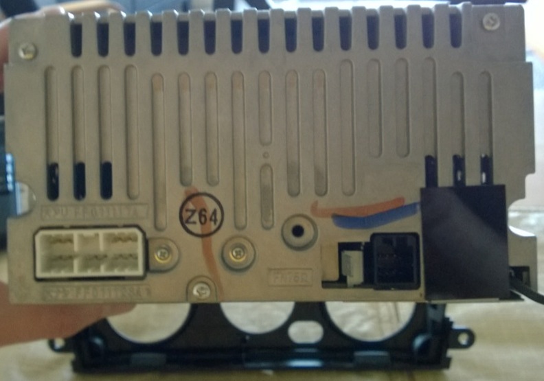
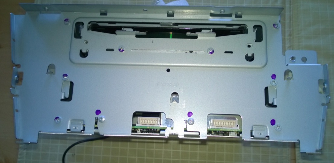
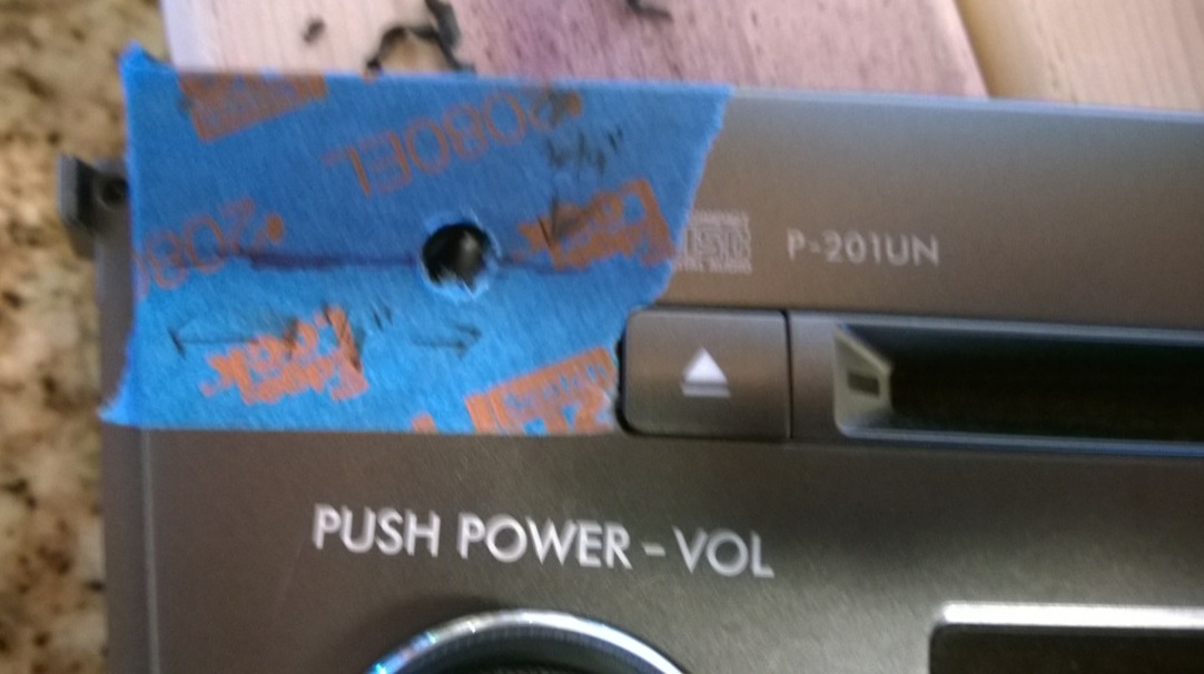
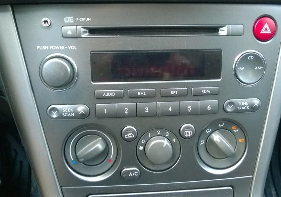
A few images of the uninstalled stereo before any disassembly. (So I could remember how to reassemble it!)

I wouldn’t say that this modification was extremely difficult, but it does involve:
- Soldering to surface mount components (I’m not awesome a soldering, but I have had a good amount of experience).
- The willingness to potentially trash a radio.
- Basic understanding of electrical diagrams and how switches work.
- A lot of time! I spent ~13 hours total working on this.
Total cost of components, however, was < $5.00 (and that’s probably overestimating.) Really the only component I didn’t have was the switching audio jack, which I got at my local RadioShack for $2.99. (I also picked up wire, heatshrink, etc. so…$5.00 sounded reasonable.) The actual list of parts and tools I used was:
- 1/8” Stereo Panel-Mount Phone Jack [$2.99, RadioShack #274-246]
- ~2 feet of each of green and red 22 gauge wire, ~1 foot of black 22 gauge wire.
- Soldering iron / Solder
- 3 x Alligator clip testing wires (1 black, 1 red, 1 green)
- Multimeter
- Hot glue gun / Hot glue
- Various sizes of flat/slotted and Phillips head screw drivers
- Wire strippers
- Wire cutter
- Needle nosed pliers
- Flashlight
- Drill with 1/4” drill bit and a 1/2” spade bit (plus some smaller sized drill bits for pilot holes)
Anyway, once you have the radio out you can disassemble it down to it’s bare components. (It is held together with a bunch of screws and tabs, I took pictures along each step of the way to ensure I could put it back together.)


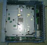
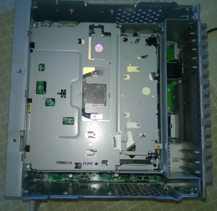
The initial steps of disassembly: the front after removing the controls, the reverse of the control unit, a top-down view after removing the top of the unit [3].
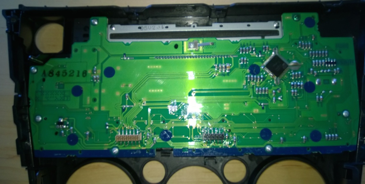
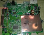
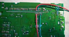
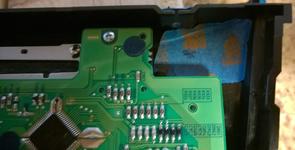
The actual circuit board of the stereo unit. You can see the radio module on the left.


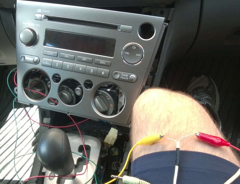
The radio module connects to the motherboard with a 36-pin connector. Pin 31 is the right audio channel and pin 32 is left audio channel. I verified this by connected the disassembled radio to the car and testing with alligator clips hooked up to my phones audio output [4]. I already knew these were the pins from the directions, but I verified by completing the circuit to these pins and ensuring I heard mixed audio with my phone and the radio.
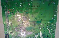
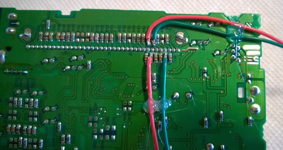
The direction suggested cutting the pin and bending it up to solder to it. I didn’t have any cutting tool small enough to get in between the pins…so I flipped the board over and did sketchier things. I scored the board to remove the traces [5] that connected the radio module to the rest of the board. I then soldered on either side of this connection to put it through the audio connector.

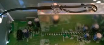
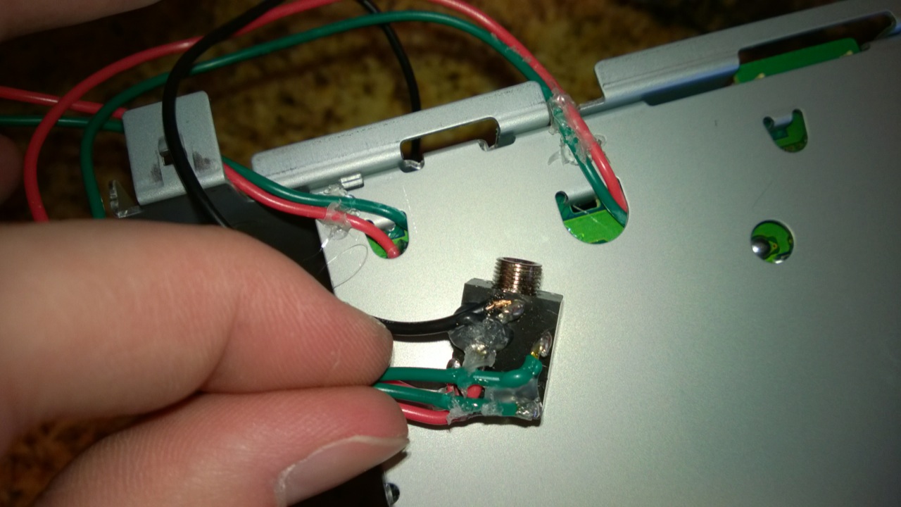
Five soldered connections are required, four to the bottom of the board [6] and one to the ground at the top of the unit.
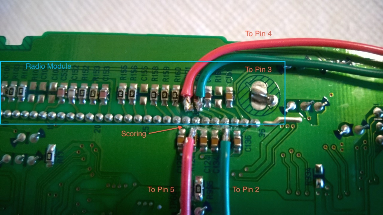

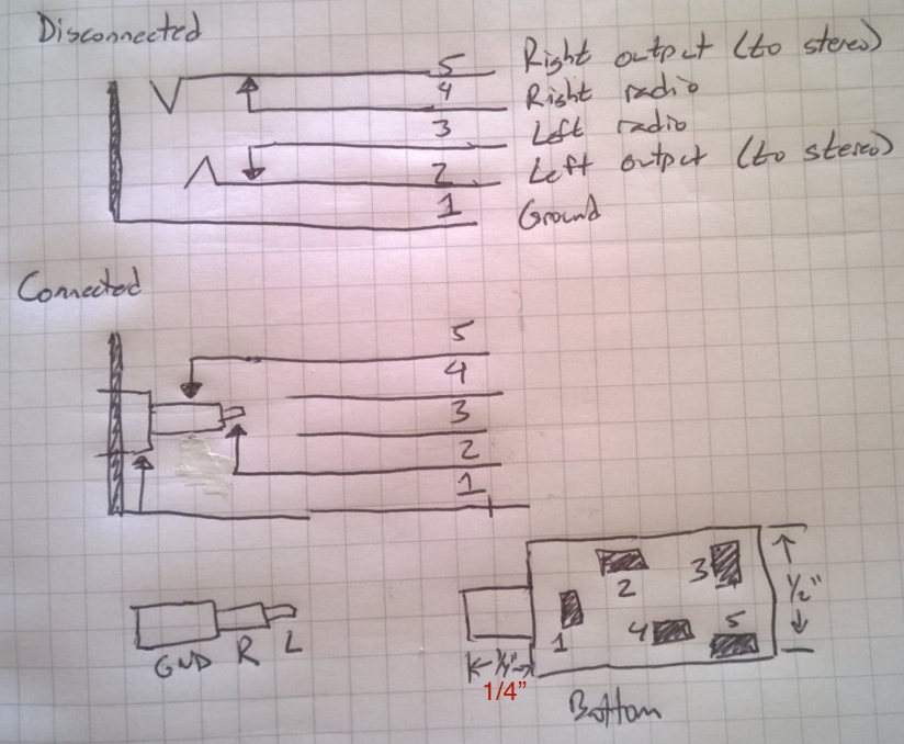
Now, the way that this works is that the audio connector output (pins 2 and 5) is always connected. If nothing is in the jack, it is connected as a passthrough to the inputs (pins 3 and 4, respectively). If an audio connector is plugged in, input redirects to the jack. (Pin 1 is ground.) For reference, red is right audio and green is left audio (black is ground).

A few of the diagrams necessary to do this. The top two diagrams are simply the connector’s two states: no plug and plug. The bottom two diagrams are a normal 1/8” audio plug and the physical pin-out and measurements of the jack.
To reiterate, pins 2 and 5 connect to the “stereo side” of the scored pins 31 and 32 of the radio module. (I.e. They are the output from the connector back to what will be played by the stereo.) Pins 3 and 4 are the inputs from the radio module side of pins 31 and 32 to the connector.
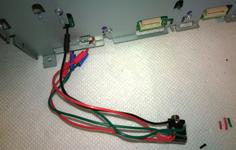
So after soldering for connections (and some hot glue), we have the ability to intercept the signal. At this point I took the bare motherboard and tested this in my car with alligator clips to ensure the radio still worked, I then connected the alligator clips to a cut audio plug to ensure everything worked.

The wires were also hot glued to the circuit board as strain relief. After reassembly I tested again with alligator clips.
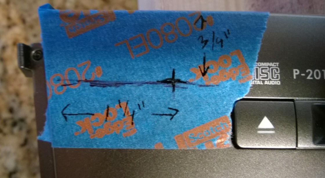
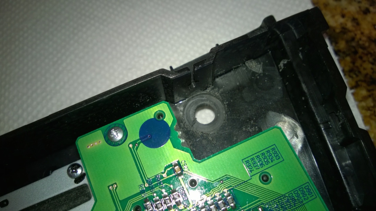
At this point, I reassembled the radio case and ran the wires out through holes in the side / bottom toward the front of the unit. I noticed there was an empty spot in the top left of the unit which looked like it would fit the panel mount audio jack. After doing some measurements I deemed my chances good enough to drill a hole here for the connector. Some tips on drilling plastic, if you haven’t done it much: use the lowest speed you can; start with very small bits and work your way up (I used 4 stages of bits); and cover both sides in masking tape to avoid scratches.
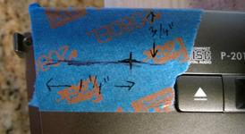
Another benefit of tape is you can write anywhere you want. These measurements were taken initially on the back and transcribed to the front (where I drilled from).

The plastic was actually too think for the panel mount connector to reach through, which is where the 1/2” spade bit came in handy. I use it to drill through roughly half the thickness of the plastic (a little at a time with lots of testing). The connector was able to nestle inside the thinner plastic and reach all the way through.


After the initial hole was drilled, the tape on the back was removed to thin the plastic.
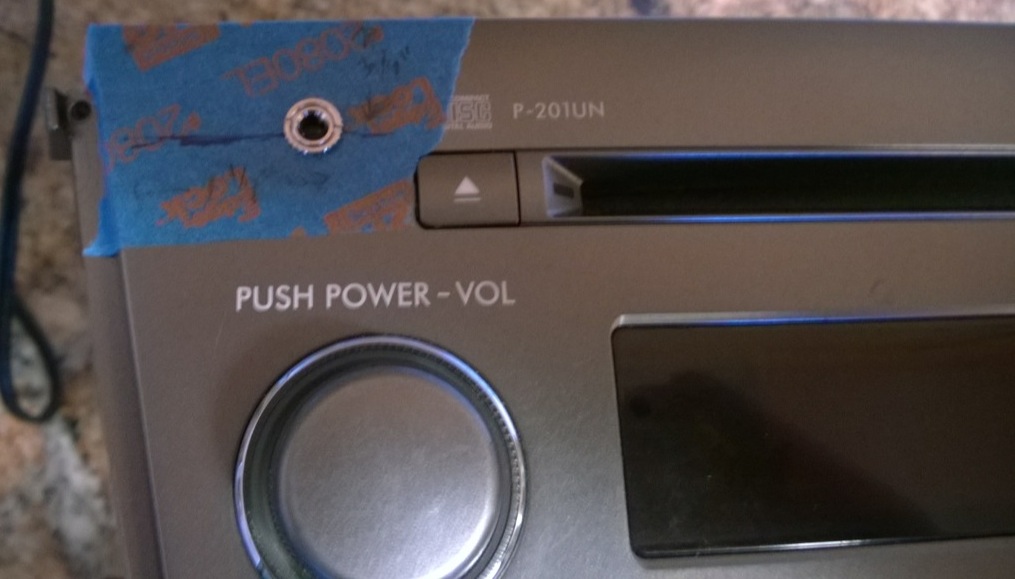
The last bit was soldering the five connections onto the audio connector, applying a coating of hot glue (for strain relief and to avoid shorts). Once the connector was soldered, the front panel was carefully reassembled. Finally, the completed unit was reinstalled back into the car and voila, I now have an auxiliary audio input! Can’t wait to test it out on a long car trip.
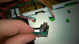
The soldered and hot-glued audio jack.

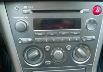
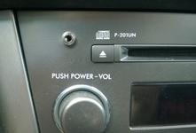
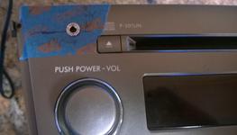
The final installed stereo unit.

One caveat of doing this (and I’m unsure if this is because I didn’t cut the pins as suggested or if this is just a fact of doing it this way…). If you have an auxiliary input device playing AND play a CD, the audio mixes instead of being replaced by the auxiliary device. It works fine on radio though, so just remember to set the stereo to FM.
| [1] | The head unit of the stereo is directly built into the dashboard and includes the heat / air conditioning controls. People do sell kits to convert the dash into one that can accept an aftermarket radio…but where’s the fun in that? |
| [2] | The 2007 edition had an option for a stereo with satellite radio and an AUX input. I probably could have bought this stereo and installed it, but I was quoted $285 last time I asked about changing my radio. |
| [3] | You can see I actually had a CD in the CD player when I removed the radio. Oops! Luckily it was just a copy of one of my CDs (I never take originals in my car). I didn’t end up scratching it or anything either! |
| [4] | Playing one of my favorite albums: No Control by Bad Religion |
| [5] | This might seem insane, but I was fairly certain I’d be able to solder a jumper back into place if everything didn’t work, so I actually felt more comfortable doing this than cutting the pin. |
| [6] | Please don’t judge my soldering! Two of the four connections were a little sloppy (I had to add solder to those instead of just tinning the wires). I did ensure there were no shorts with a multimeter (and had to resolder one connection). |